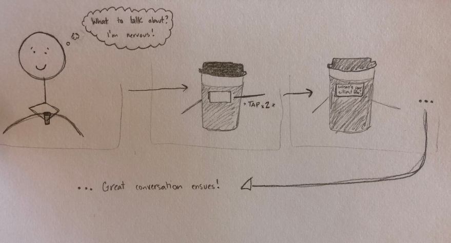
Ever been on an awkward coffee date/meeting? Let our product give you an ice breaker before the silence kills the vibe! Our to-go cup sleeve will print a message right on the screen. If it goes really well, we even have second date ideas all at the tap of your finger.
To-Go Coffee Mug Sleeve
Part 1: Project Proposal
WHY
Reduce uncomfortable silences during coffee dates! Intended to be used over coffee with a friend, first date, or long-time-no-see acquaintance.
WHAT
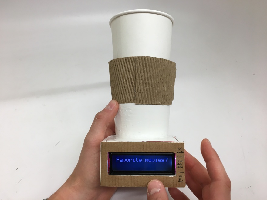
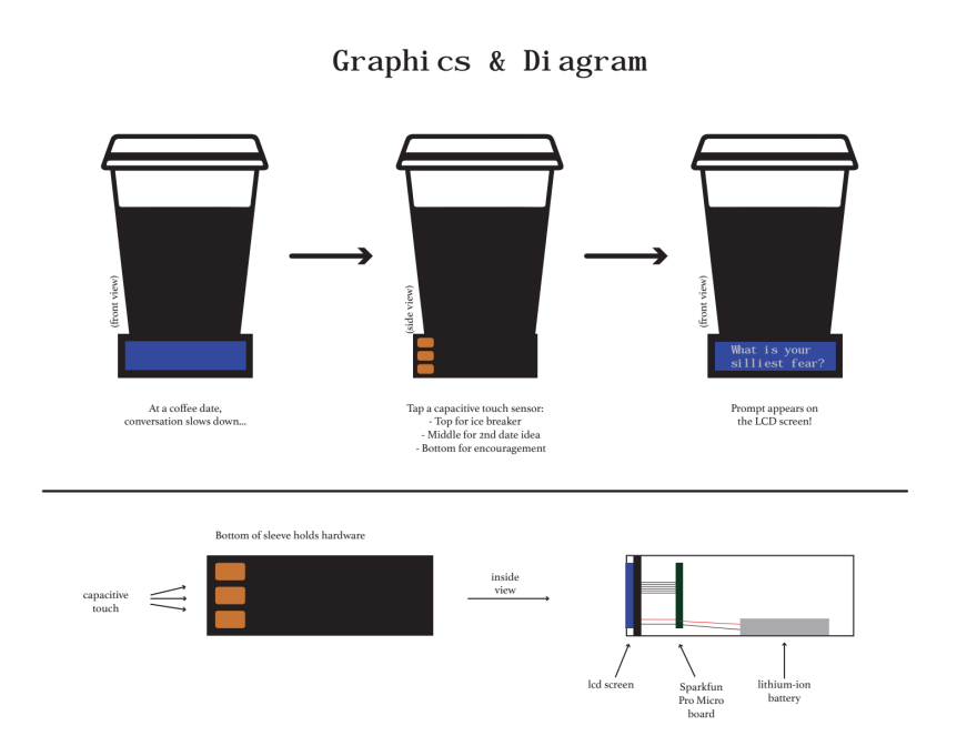
A sleeve to set to-go coffee mugs in to facilitate conversations. Pressure sensors are listening for a certain number of taps (input), and based on the number of taps (processing) the LCD screen displays a conversation prompt, question, or encouragement (output).
HOW
3D print an enclosure (that a to-go coffee mug can rest in) housing the LCD screen and microcontroller. Pressure sensors will be on either side and below the screen will be picking up tapping signals. No LCD screen responses will be triggered by simply holding the cup. For 2 taps: display an ice breaker/get to know the person question to stimulate better conversations. For 3 taps: displays a prompt to move things along for planning future meetings/dates. For a long series of rapid taps: the user is nervous, so an encouraging message is displayed. Each category of LCD displays has several phrases stored, so the cup randomly chooses one to display each time the user inputs the respective amount of taps.
MATERIALS
- LCD screen (rechargeable)
- charger
- Pressure sensors
- 3D printing filament
- Arduino (rechargeable?)
- Material to make exterior pleasing
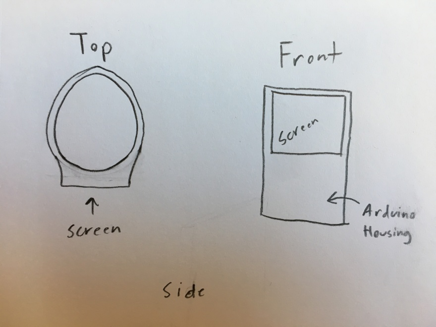
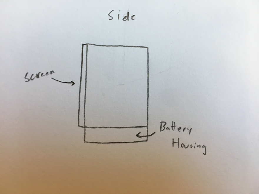
DRAWING
INTERACTION
QUESTIONS
- Recommendations for specific microcontrollers?
- What LCD screen are we skilled enough to program that is in our budget?
Part 2: Preparation for User Testing
To begin making our coffee cup sleeve, we split the project into the programming of the LCD screen and the 3D printing of the enclosure. We bought an Adafruit Feather board, a micro-controller noted for its small size and wide versatility, and an Adafruit 16×2 LCD screen.
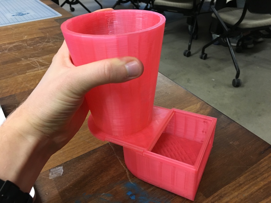
My project partner Jason designed the .stl file to 3D print the sleeve itself. We quickly decided that putting all the hardware in an enclosure on the bottom of the cup would be more stable, and easier to connect each component (screen, board, and battery). Here is the enclosure that Jason designed.
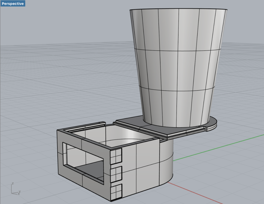
Unfortunately, it was much too wide and uncomfortable to hold. So we decreased the size and planned to print it again before the final product was finished.
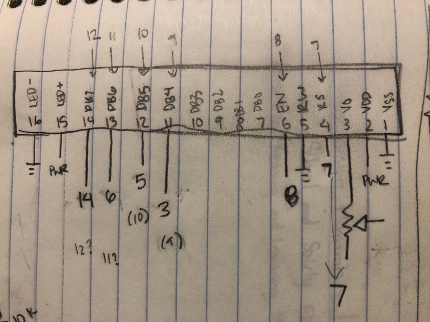
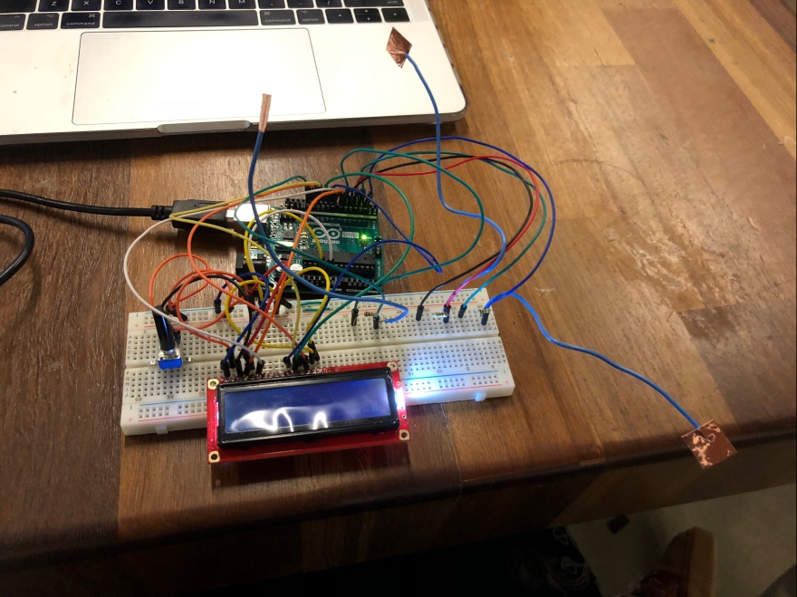
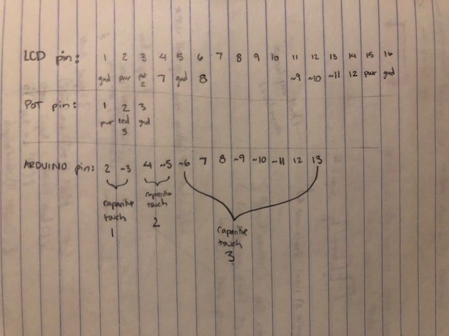
Unfortunately, wiring and programming the LCD screen also was off to a rough start. Clearly from this very complicated chart I drew, it took me several tries to wire the LCD screen correctly, and I had to slowly gain a conceptual understanding of what each connection meant in order to make it work.
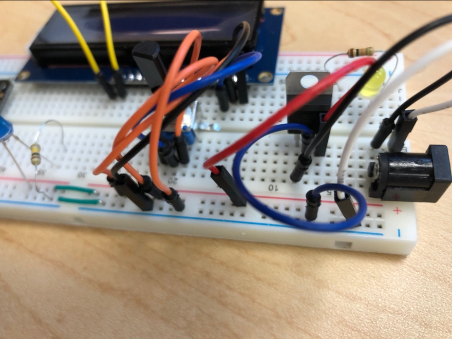
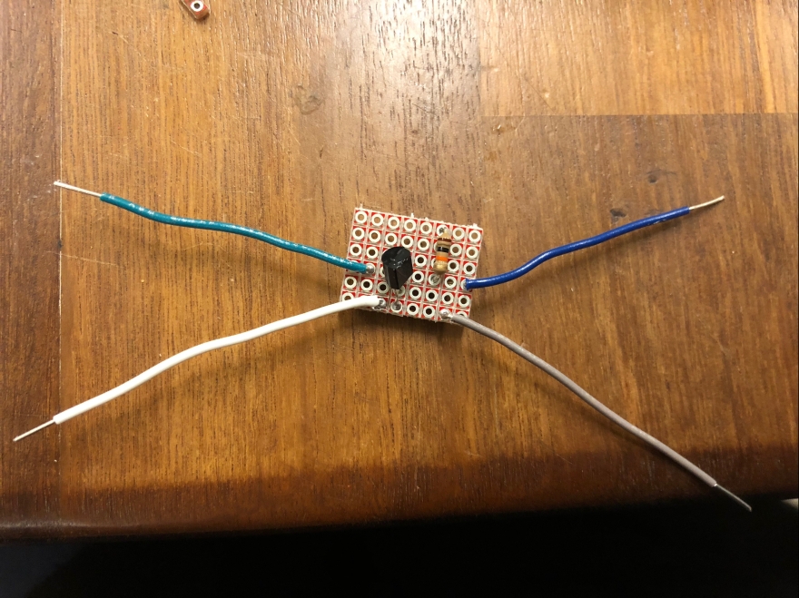
First, I was struggling to wire the backlight and logic of the screen, so I put an LED light on the breadboard to make it more clear where my current was running. I also had figured out that the Feather board only put out 3.3V and the LCD screen needed 5V, so I set up a second power source and power regulator to give the screen 5V. While this got the Logic and contrast functioning, in order fully solve the problem we would need a different board.
First we tried to make our own 3.3V to 5V boost, but that was entirely unsuccessful. The idea was to convert the 3.3V signal from the Feather board to make it compatible with the LCD screen, but since we didn’t understand to look for Voltage compatibility in the first place, we didn’t have the skills to work around it. Long-term, the best idea was to use a different board.
So, we replaced it with a Sparkfun Pro-Micro board. It is also very small and has 5V capability. When we connected the LCD screen to the Pro-Micro board, we finally got characters to display, although they were not English letters.
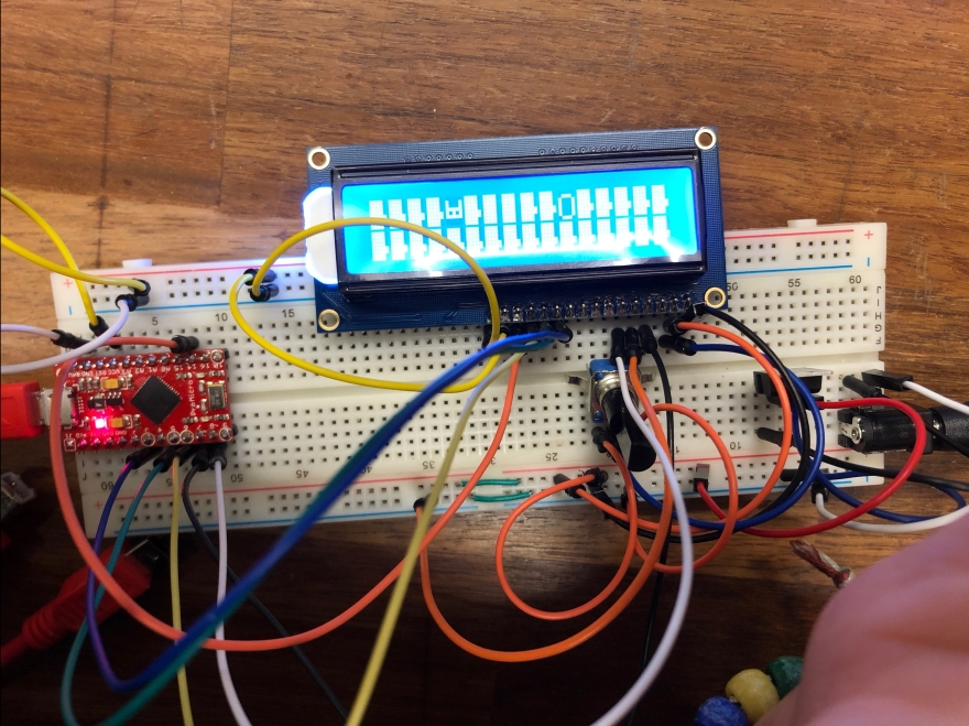
With some slight modification to the code, an understandable message finally made it onto the screen. Since the Pro-Micro board was still giving us inconsistent results and we hadn’t gotten our system running on one power source, we still had some changes to make after user testing.
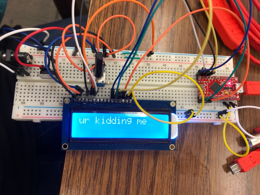
So, we presented our interaction schematics, the Rhino 3D model file, and the screen with our simple message on it at user testing.
Part 3: Development Toward Final Product
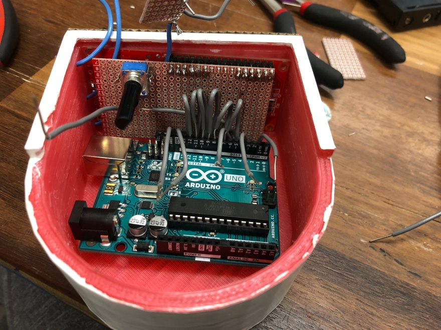
After having several obstacles with the various boards, I decided to get the code working with our LCD screen on an Arduino Uno board, one I was familiar with using. When it still wasn’t working, I thought to try a different LCD screen, in case the Adafruit one was faulty.
Turns out, the replacement screen worked on the first try. I quickly got the capacitive touch sensors successfully incorporated, and each one was producing the responses we needed. One prompted an ice breaker, the second prompted a second date idea, and the third displayed encouragements on the screen.
Here is my final code:
This file contains hidden or bidirectional Unicode text that may be interpreted or compiled differently than what appears below. To review, open the file in an editor that reveals hidden Unicode characters.
Learn more about bidirectional Unicode characters
| /* | |
| Here is the code for project 1! We built a to-go coffee cup sleeve that gives the user conversation starters. The messages were prompted by capacitive touch sensors, and printed onto an LCD screen. | |
| I got the original LCD screen 'hello world' code from this url: http://www.arduino.cc/en/Tutorial/LiquidCrystalHelloWorld | |
| */ | |
| // include the library code: | |
| #include <LiquidCrystal.h> | |
| #include <CapacitiveSensor.h> | |
| // initialize the library by associating any needed LCD interface pin | |
| // with the arduino pin number it is connected to | |
| //const int rs = 12, en = 11, d4 = 5, d5 = 4, d6 = 3, d7 = 2; | |
| LiquidCrystal lcd(7, 8, 9, 10, 11, 12); | |
| int button1 = 0; | |
| int button2 = 1; | |
| int button3 = 0; | |
| int buttonState = 0; | |
| // message arrays | |
| String convos[6] = {"What do you like to do in your free time? ","Are you more of an indoors or outdoors person? ","Favorite movies? ","Where have you traveled? ","What is your favorite food? ","What was the last show you binged? "}; | |
| String secondDate[10] = {"Cook something easy together","Go to an amusement park","Get your fortunes told","Find a public swimming pool that’s open at night","Pack a picnic, and go for a hike","Go to drinks with a view","Visit an old-fashioned ice cream parlor","Hit the local farmers market","Make chocolate martinis together","Hit up a jazz club"}; | |
| String help[8] = {"You got this!","Hi hot stuff","Don't panic!","Great smile","10 / 10","You're cute","You're like a sharpie – super fine","Drinking hot tea? You hottie"}; | |
| // initialize capacitive touch sensors | |
| CapacitiveSensor cs_2 = CapacitiveSensor(5,4); | |
| CapacitiveSensor cs_3 = CapacitiveSensor(3,2); | |
| CapacitiveSensor cs_4 = CapacitiveSensor(6, 13); | |
| void setup() { | |
| // set up the LCD's number of columns and rows: | |
| lcd.begin(16, 2); | |
| // Print a message to the LCD. | |
| //lcd.print("this is my nightmare"); | |
| pinMode(2, INPUT); | |
| Serial.begin(9600); | |
| } | |
| void loop() { | |
| long sensor1 = cs_2.capacitiveSensor(30); | |
| long sensor2 = cs_3.capacitiveSensor(30); | |
| long sensor3 = cs_4.capacitiveSensor(30); | |
| // if the first sensor is pressed, display an ice breaker message | |
| if(sensor1 > 400){ | |
| int number1 = random(0,5); | |
| String message1 = convos[number1]; | |
| //Serial.println(message1); | |
| lcd.clear(); | |
| lcd.print(message1); | |
| delay(1000); | |
| //to move it offscreen left: | |
| for (int positionCounter = 0; positionCounter < 20; positionCounter++) { | |
| // scroll one position left: | |
| lcd.scrollDisplayLeft(); | |
| // wait a bit: | |
| delay(250); | |
| } | |
| } | |
| // if the second sensor is pressed, display a second date idea | |
| if(sensor2 > 400){ | |
| int number2 = random(0,9); | |
| String message2 = secondDate[number2]; | |
| //Serial.println(message2); | |
| lcd.clear(); | |
| lcd.print(message2); | |
| delay(1000); | |
| //to move it offscreen left: | |
| for (int positionCounter = 0; positionCounter < 20; positionCounter++) { | |
| // scroll one position left: | |
| lcd.scrollDisplayLeft(); | |
| // wait a bit: | |
| delay(250); | |
| } | |
| } | |
| // if the third sensor is pressed, display an encouraging message | |
| if(sensor3 > 400){ | |
| int number3 = random(0,7); | |
| String message3 = help[number3]; | |
| //Serial.println(message3); | |
| lcd.clear(); | |
| lcd.print(message3); | |
| delay(1000); | |
| //to move it offscreen left: | |
| for (int positionCounter = 0; positionCounter < 20; positionCounter++) { | |
| // scroll one position left: | |
| lcd.scrollDisplayLeft(); | |
| // wait a bit: | |
| delay(250); | |
| } | |
| } | |
| } |
In order to absorb the new screen into our enclosure, (that we re-printed), I measured the dimensions and compared them to the Adafruit dimensions that we had printed with.
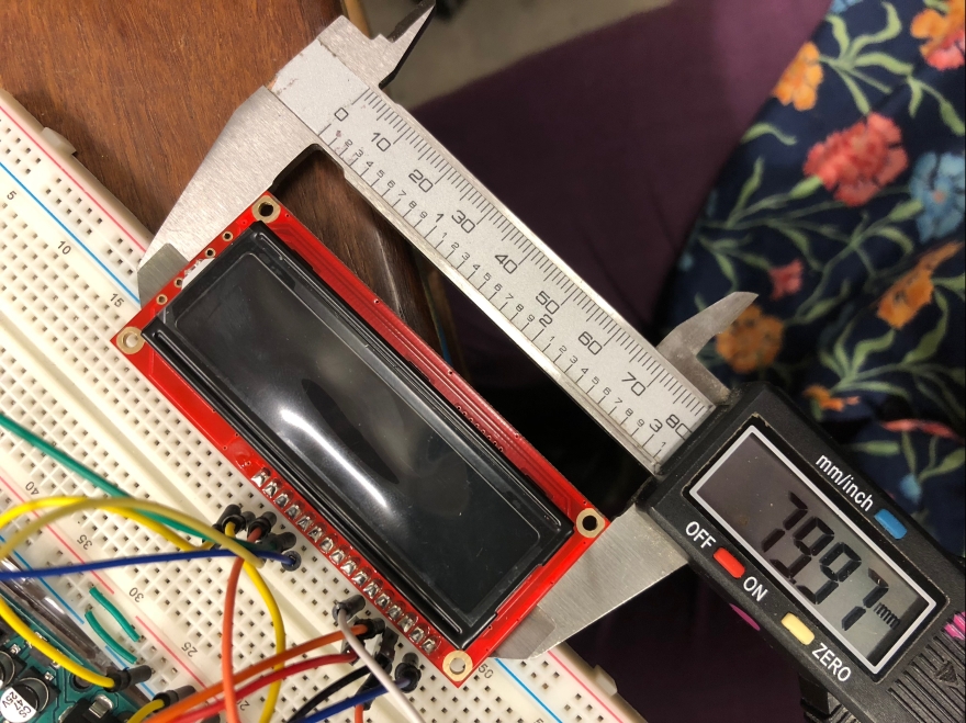
Unfortunately the Sparkfun screen was slightly bigger than the original Adafruit screen, so we had to file our enclosure to fit the new component.
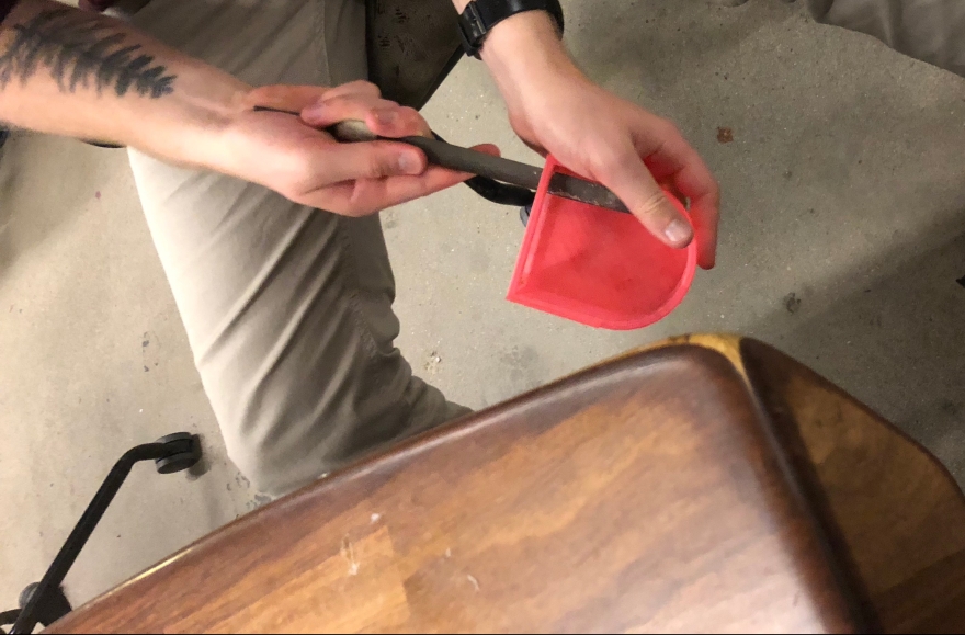
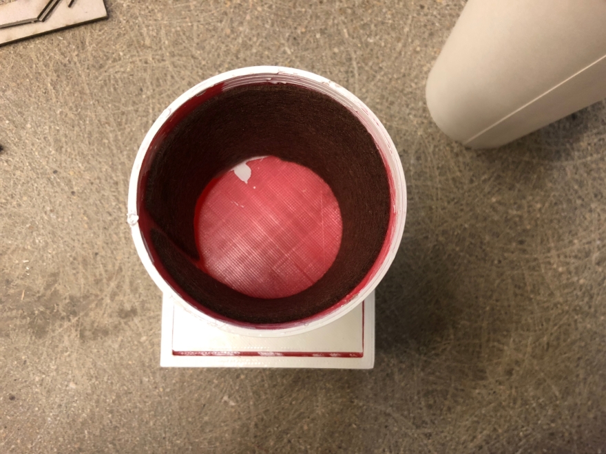
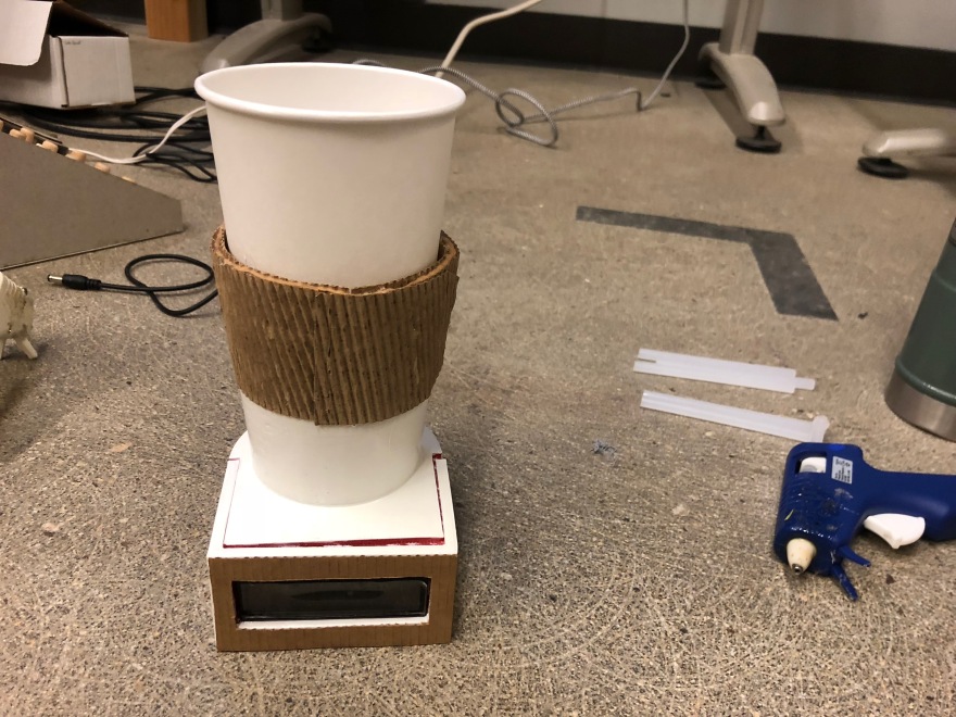
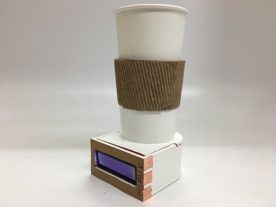
After the enclosure was sanded and filed to fit our parts, we painted it white to polish the aesthetic of our project. We also lined the cup with felt to make to-go coffee cups fit better in our sleeve.
I added a cardboard grip to emulate a real to-go sleeve, and there is cardboard bordering the screen so I could label which touch sensor prompted which type of message.
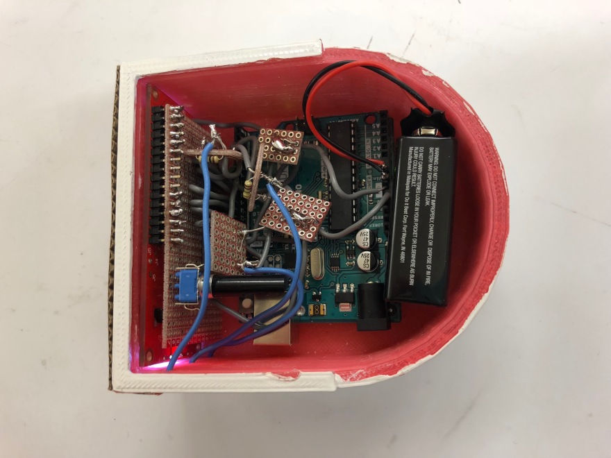
Now that we had all of the electronics working together successfully, and the exterior of the cup was polished, it was time to fit our components into the cup itself. It took a while to solder each of the connections, and in order to do it correctly we were very deliberate about the order and the pace at which we did so. We wrote out each and every connection we had to solder to prevent confusion.
We fit a 9V battery into the enclosure by soldering the power and ground wires to header pins, and connected it to the Vin power pin. The rest of our components were plugged into the 5V power pin to ensure that they did not receive too much voltage.
It was hard to fit everything into our enclosure, but not impossible.
Finished Result
In the end, it all came together very well!
Unfortunately, the soldering connections were not perfect, so after a while the capacitive touch sensors did not function as perfectly consistent as they had when we originally put everything in our enclosure.
Reflection
In hindsight, this project has taught me a couple things about creating physical computing objects. With regards to ordering components, I now know to check for how well they can work together. Beyond that, I will plan out the whole trajectory of my project and hopefully solve more problems before they arise. I will consider space constraints of my enclosure, and give myself more time to solder and troubleshoot after all the components are put together. Timelines and milestones are important to stay consistent with, but I learned that you need to leave extra time to absorb any problem that are inevitably going to arise. All in all, I had a lot of fun making this to-go cup! And I like to imagine the possibilities of where a product like this could go.
