Digital I/O and Soldering
In this lab, we were introduced to soldering & prototyping boards, as well as exploring the use of Arduino with basic digital input/output functions.
Part 1: Soldered Breakout Board
In order to learn about the advantages of moving circuits away from breadboards, we soldered a basic circuit to a breakout board. I chose to do a circuit with two yellow LEDs in parallel with each other. I also included two wires so I could connect my circuit to power and ground.
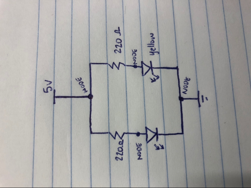
Below is a photo of my schematic for part one of the lab. Each of the labeled nodes is a soldering point. Since I used two yellow LEDs, I used 220 ohms resistors to moderate the 5V of current.
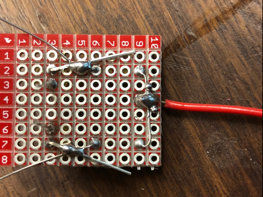
First, I placed the red power wire and the two resistors neatly into one end of my breakout board. I made sure to leave space for the rest of the circuit on the other half.
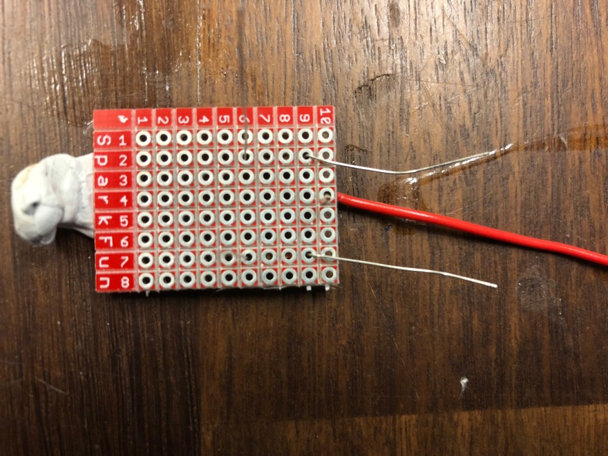
In order to secure these parts before moving on to actually building the circuit, I soldered them into place. 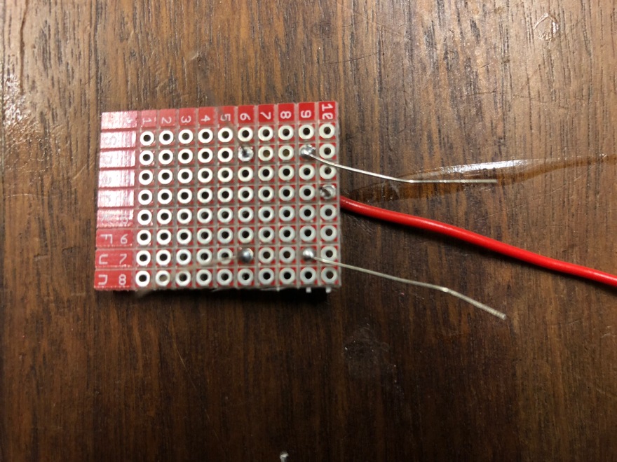
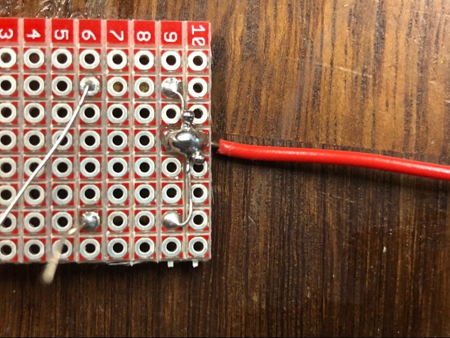
Now that I could work with my resistors and power wire without them moving everywhere, I bent the resistors to connect with the power wire and soldered that connection. After all three wires were connected I clipped the excess off with the diagonal wire cutters to clean it up a little bit.
Next I added the LEDs, making sure to put the long end close to the remaining resistor wire to allow the current to flow. I soldered the long remaining resistor wire to the positive-side wire on the LEDs.
I also clipped the excess wire from those two connections as well. Next, I attached the yellow grounding wire to the opposite side of my breakout board as the red power wire.
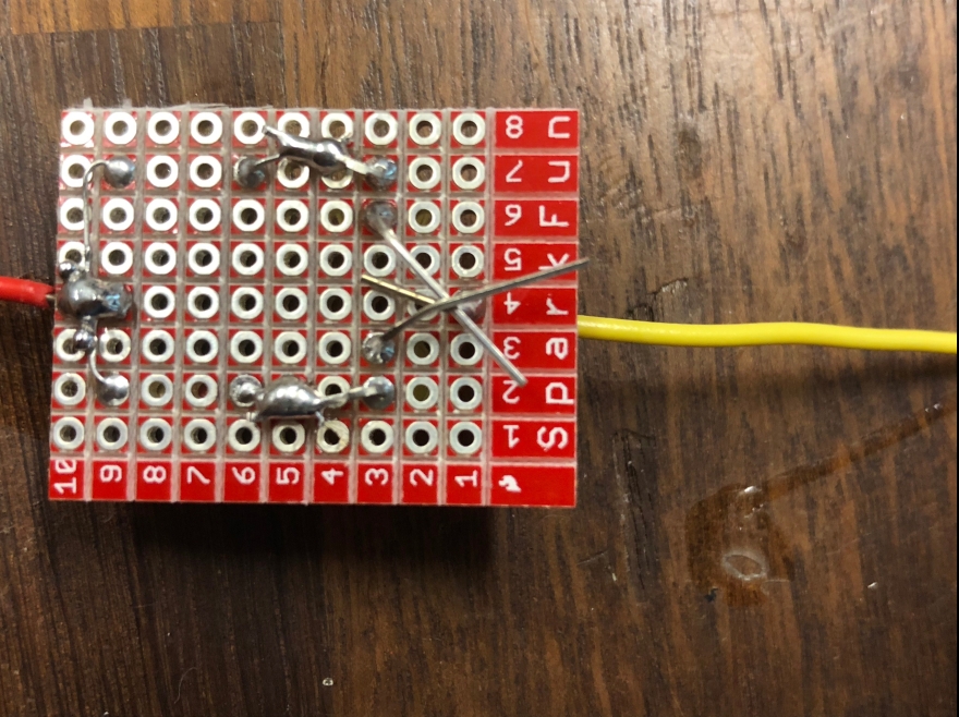
After soldering the LEDs to the ground wire and clipping the excess, here is a picture of my finished circuit!
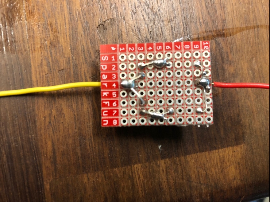
And the front side:

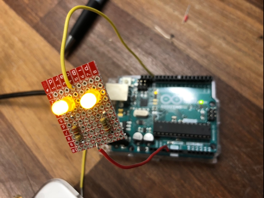
It works!
Part 2: Digital Input and Output
To complete the second half of the lab, I build a circuit with two different digital inputs. I used two momentary switches (buttons). Each one had a different output onto my neopixel, and if both were pressed at the same time there was a third output.
First, I set up my breadboard, neopixel, and Arduino to make sure that all the connections were working before I trouble-shot the buttons at all. To do this I just used some example code that we wrote in class (turns each of the lights on the neopixel teal).
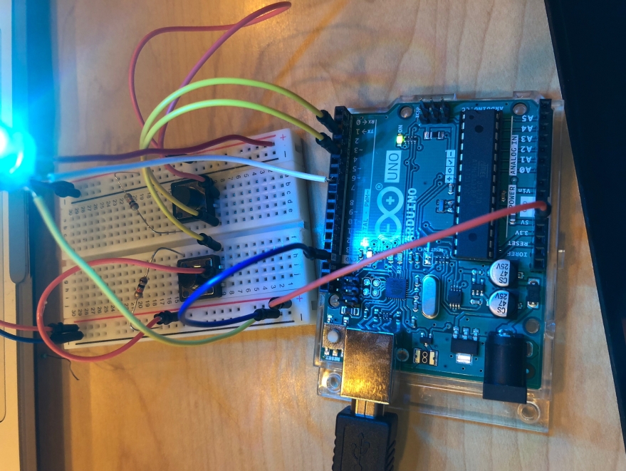
Next, I began to test the functionality of the buttons. To do this I used a debugging function in Arduino to see if my inputs (buttons) would switch from 0 to 1 when pressed. In my code lines 29 & 45 show the function. My original breadboard setup had many errors with the wiring of the buttons, so my final layout looks a little different.
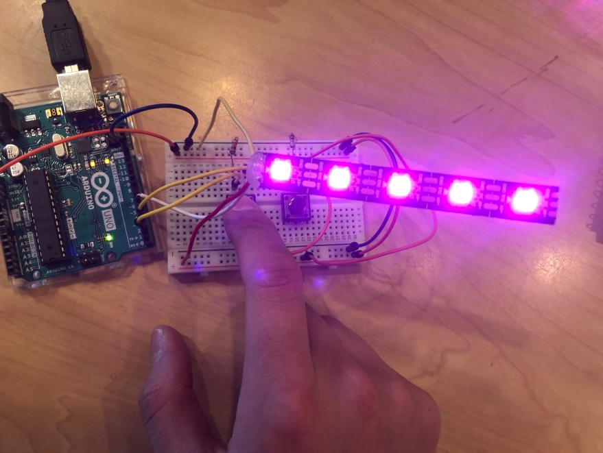
Below is the final code I used from this lab. If button 1 is pressed and held, the lights turn magenta one by one. Since the neopixels are so bright, they turn off one by one when the button is released to make it a little easier to look at.
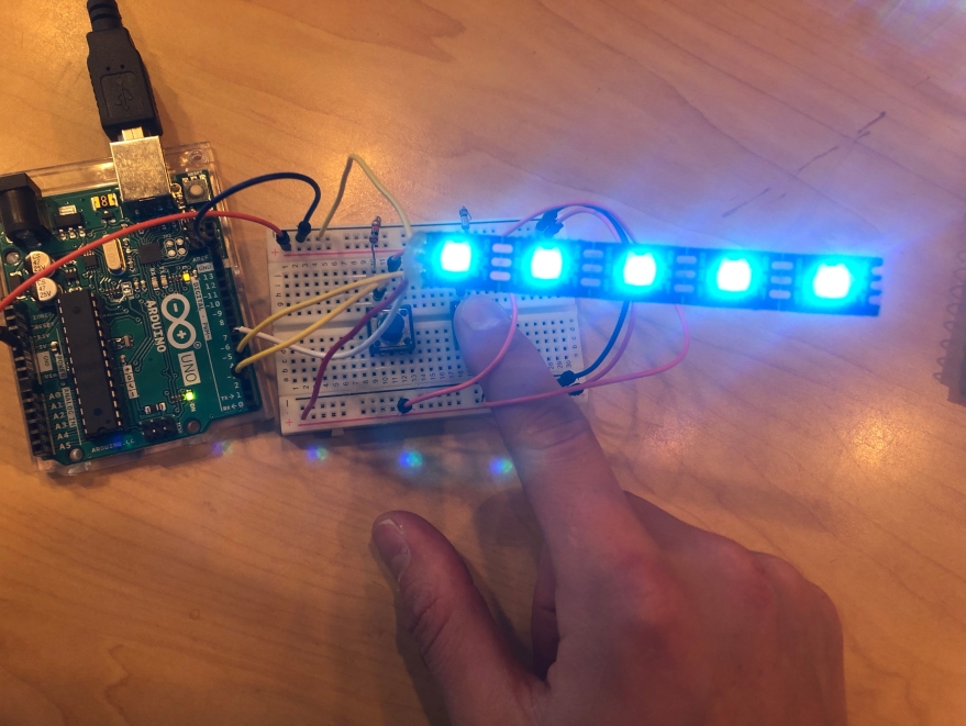
If button 2 is pressed and held, it has the same process as button 1 except the lights turn light blue.
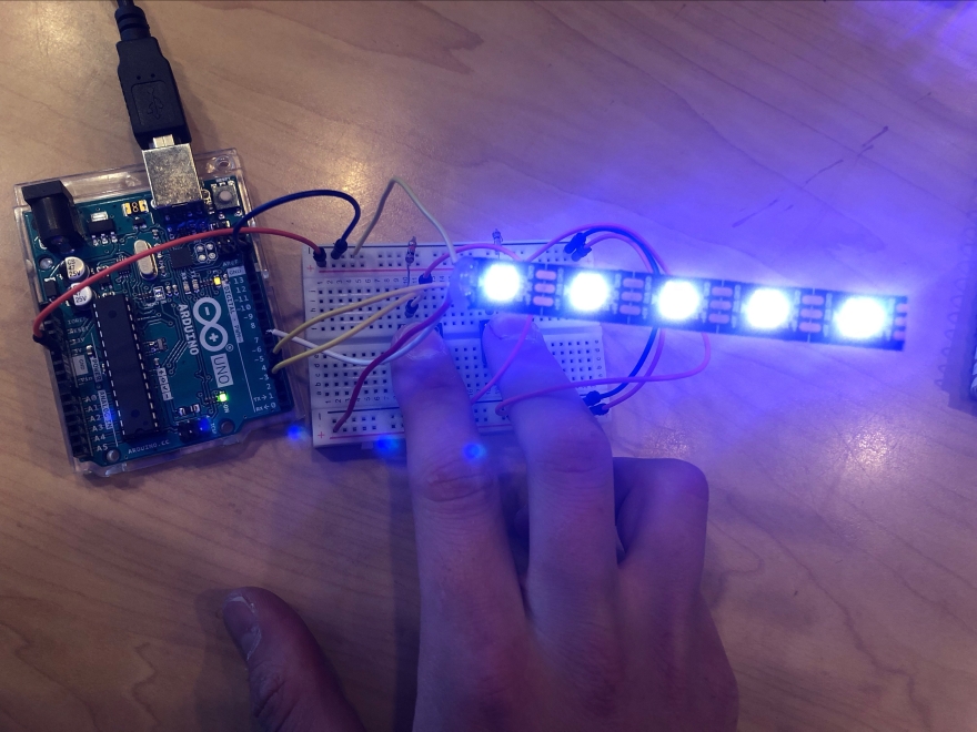
Lastly, if both are pressed together, the lights turn purple! In the photos it looks close to white/lavender, but that is just due to how bright the lights are.
This file contains hidden or bidirectional Unicode text that may be interpreted or compiled differently than what appears below. To review, open the file in an editor that reveals hidden Unicode characters.
Learn more about bidirectional Unicode characters
| #include <Adafruit_NeoPixel.h> | |
| #ifdef __AVR__ | |
| #include <avr/power.h> | |
| #endif | |
| // pint that the strip is connected to | |
| #define PIN 7 | |
| // strip is a variable (instance of neopixel library) | |
| // first argument is number of pixels, then pin number | |
| Adafruit_NeoPixel strip = Adafruit_NeoPixel(5, 7, NEO_GRB + NEO_KHZ800); | |
| // define button pins | |
| const int button1 = 2; | |
| const int button2 = 4; | |
| int button1State = 0; // changing from 0 and 1 (digital) | |
| int button2State = 0; // changing from 0 and 1 (digital) | |
| void setup() { | |
| // initialize the strip | |
| strip.begin(); | |
| strip.show(); // sets all pixels to 'off' | |
| // initialize buttons as input | |
| pinMode(button1, INPUT); | |
| pinMode(button2, INPUT); | |
| // establish serial comm for debugging | |
| Serial.begin(9600); | |
| } | |
| void loop() { | |
| // first set the pixel color, then you show them | |
| // setPixelColor(n, red, green, blue); n is the pixel # | |
| // 0 is closest to the arduino | |
| // r g b are values 0 – 255 | |
| // strip.setPixelColor(0, 0, 150, 150); | |
| // strip.setPixelColor(2, 150, 0, 150); | |
| // strip.show(); | |
| button1State = digitalRead(button1); | |
| button2State = digitalRead(button2); | |
| Serial.println(button2State); | |
| // if button 1 is pressed, turn LEDs red/pink from bottom to top | |
| if((button1State == HIGH) && (button2State == LOW)){ | |
| for(uint16_t i = 0; i < strip.numPixels(); i++){ | |
| strip.setPixelColor(i, 191, 10, 48); | |
| strip.show(); | |
| delay(500); | |
| } | |
| } | |
| // if button 2 is pressed, turn LEDs blue/teal from bottom to top | |
| else if((button2State == HIGH) && (button1State == LOW)){ | |
| for(uint16_t i = 0; i < strip.numPixels(); i++){ | |
| strip.setPixelColor(i, 0, 128, 129); | |
| strip.show(); | |
| delay(500); | |
| } | |
| } | |
| // if both are pressed, turn LEDs purple/lavender from bottom to top | |
| else if((button1State == HIGH) && (button2State == HIGH)){ | |
| for(uint16_t i = 0; i < strip.numPixels(); i++){ | |
| strip.setPixelColor(i, 107, 63, 160); | |
| strip.show(); | |
| delay(500); | |
| } | |
| } | |
| // else, all lights are off | |
| else if((button1State == LOW) && (button2State == LOW)){ | |
| for(uint16_t i = 0; i < strip.numPixels(); i++){ | |
| strip.setPixelColor(i, 0, 0, 0); | |
| strip.show(); | |
| delay(500); | |
| } | |
| } | |
| } |
Here are photos of the final product:
Red!
Blue!
Purple!
Video of the lights cycling through all of the options. Experimenting with this was a really cool example to me of how the Arduino is always listening to the inputs, and it switched outputs without me having to re-upload the code or anything. I knew that was possible, I just appreciated seeing it in action!
