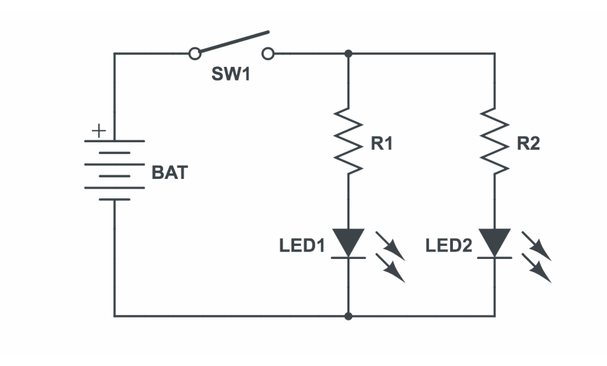
Simple Circuits & DIY Switch
For the first lab in Object, we had to create a simple circuit on a breadboard and then add a creative touch by making a DIY switch with a clever encasing to hide the software. We practiced making circuits in series and in parallel, and ultimately my lab had 3 LEDs in parallel. I made mine look like flowers and a bee, here is the process I followed!
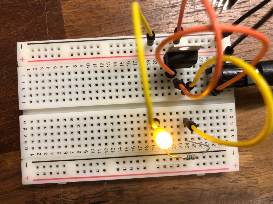
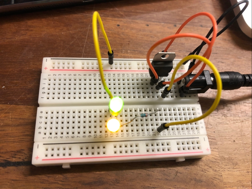
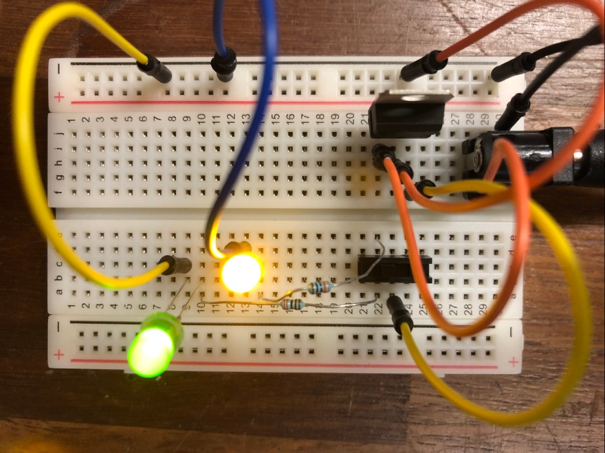
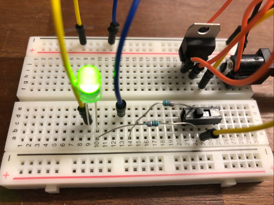
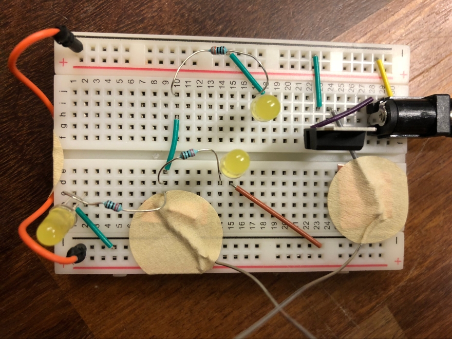
First, I had to become comfortable moving from a schematic to a circuit on a breadboard, so I practiced a couple times before moving into the actual lab. Which turned out to be very helpful because I was pretty out of practice using a breadboard, and needed to refresh myself on how to complete circuits. Here is a photo of my first successful circuit!
The 9V power source goes directly to the voltage regulator, which sends 5V into the circuit. I used a 220 Ohm resistor because the yellow LED takes 2V and has a current of 20 mA, so to calculate resistance I did power in minus power of the load, 5V – 2V, and divided it by current, 0.02A, and got 150 Ohms. Since 220 is the next biggest resistor it was appropriate for me to use it.
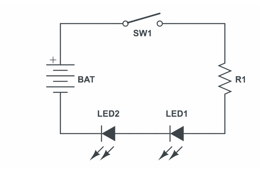
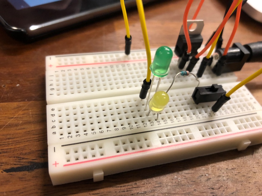
Then, I made a circuit with LEDs in series with each other. I used a green LED and a yellow LED. In order to determine which resistor I needed, I found the difference in voltage between power (5V) and the LEDs (both yellow and green are 2V), and divided it by the current of the LEDs (20 mA). Which gave me 150 Ohms, so I used the 220 resistor because that is the next highest value. Here is the schematic I used, and the completed circuit.
One way I confirmed that I had correctly arranged my breadboard so the LEDs were in series with each other is I took out one of the LEDs and the other one turned off. Which means the current could not complete the circuit, and the LEDs were truly in series.
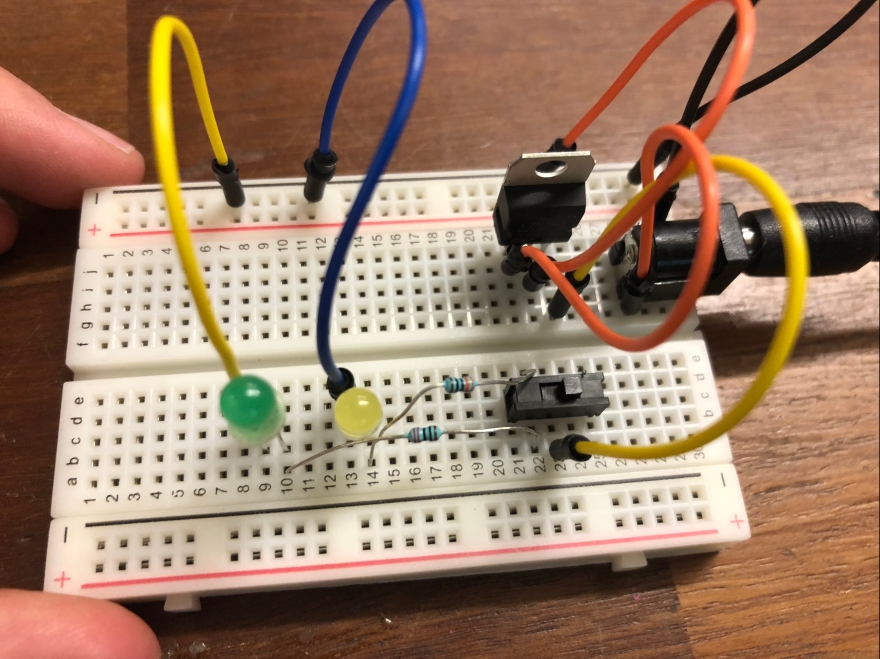
Next, I added a switch to make sure I understood how to incorporate switches into completed circuits. This was my first step towards making my breadboard interactive.
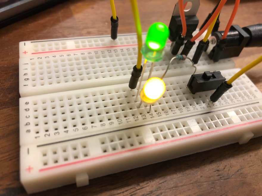
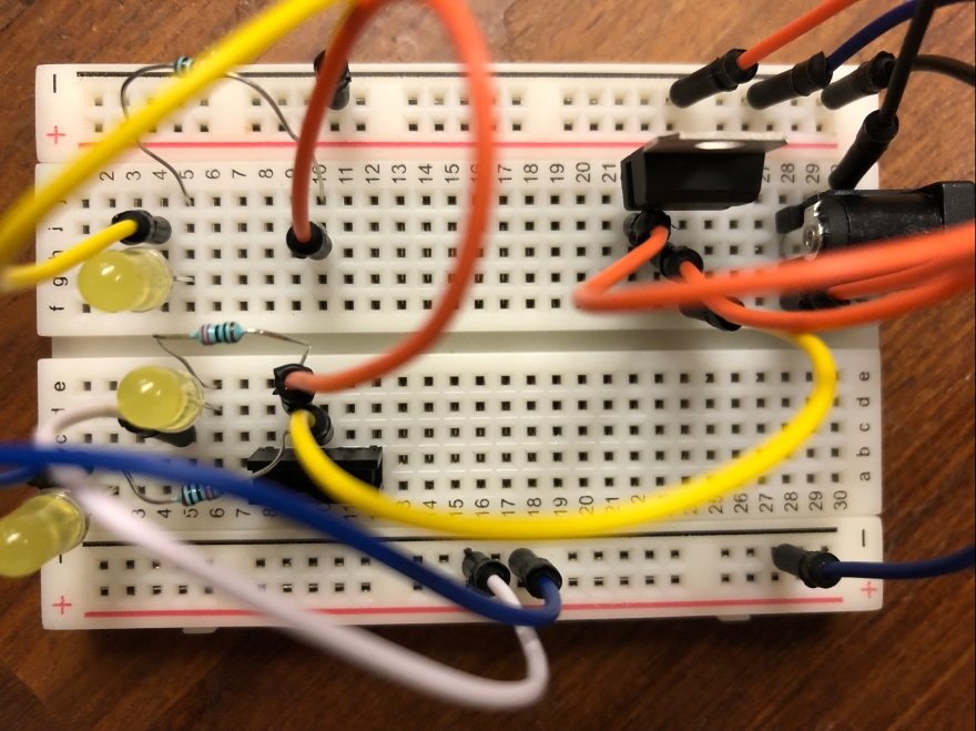
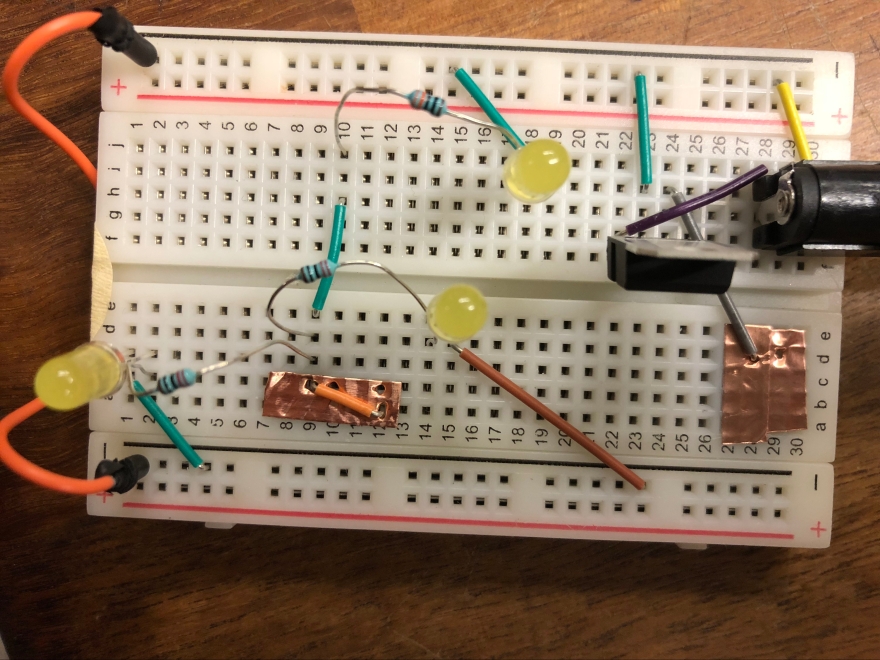
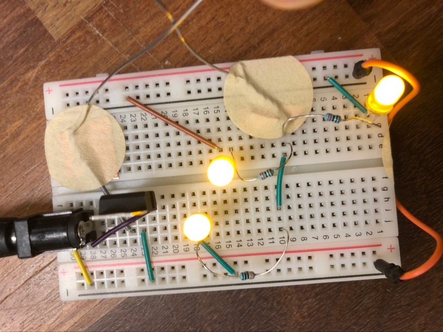
After that, I made a circuit with LEDs in a parallel configuration. I used the green and yellow LEDs again, which means I needed two 220 Ohm resistors (because yellow and green LEDs both have 5V voltage and 20 mA current). Here is the schematic that I used and the resulting breadboard arrangement.
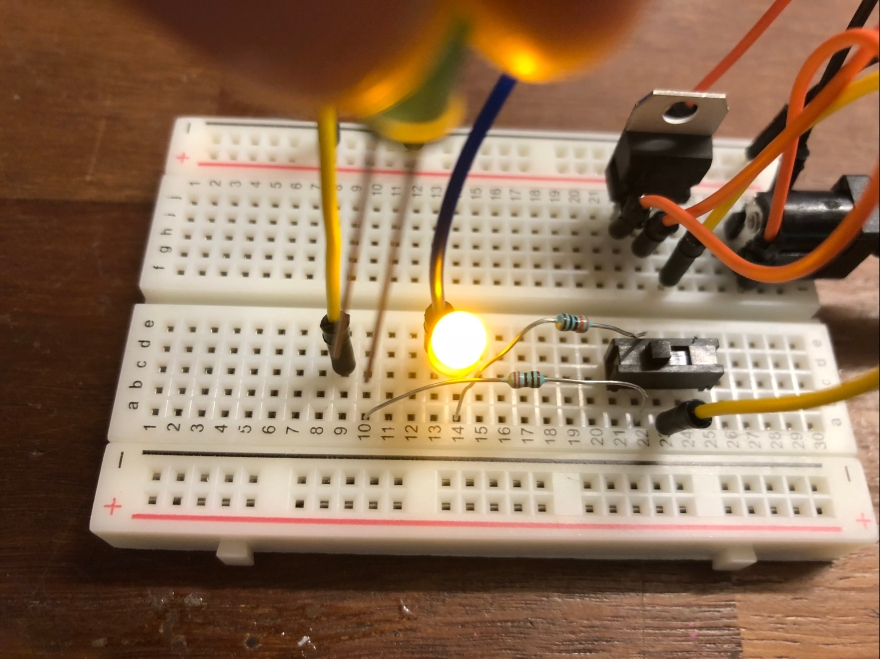
The switch works to open/close the circuit, and you can tell that the LEDs are truly in parallel with each other because when one is removed, the other stays on.
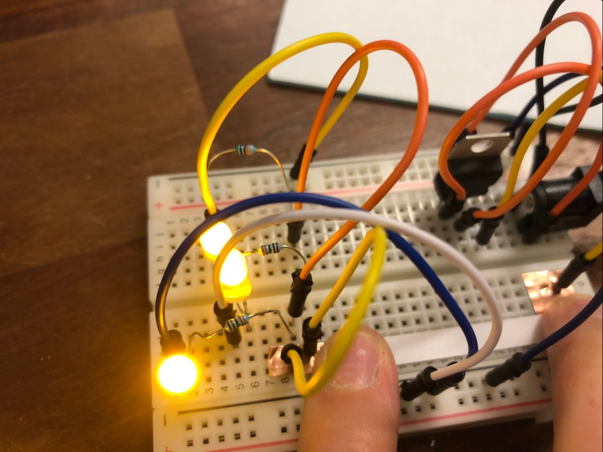
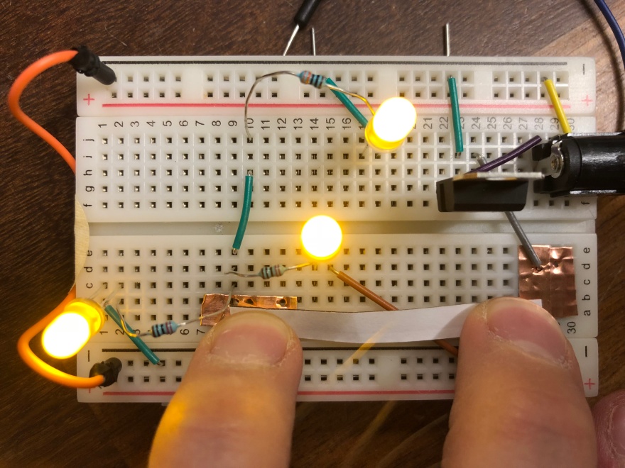
For the creative part of the lab, I wanted to use all yellow LEDs, so I reorganized my breadboard to have 3 yellow lights in parallel with each other. I chose to do a parallel arrangement because in case one got loose, the other ones would still light up the end project. This step had a couple iterations so I could optimize the distribution of the lights as well as be able to eventually incorporate my DIY switch.
I started to test the use of conductive tape to complete the circuit.
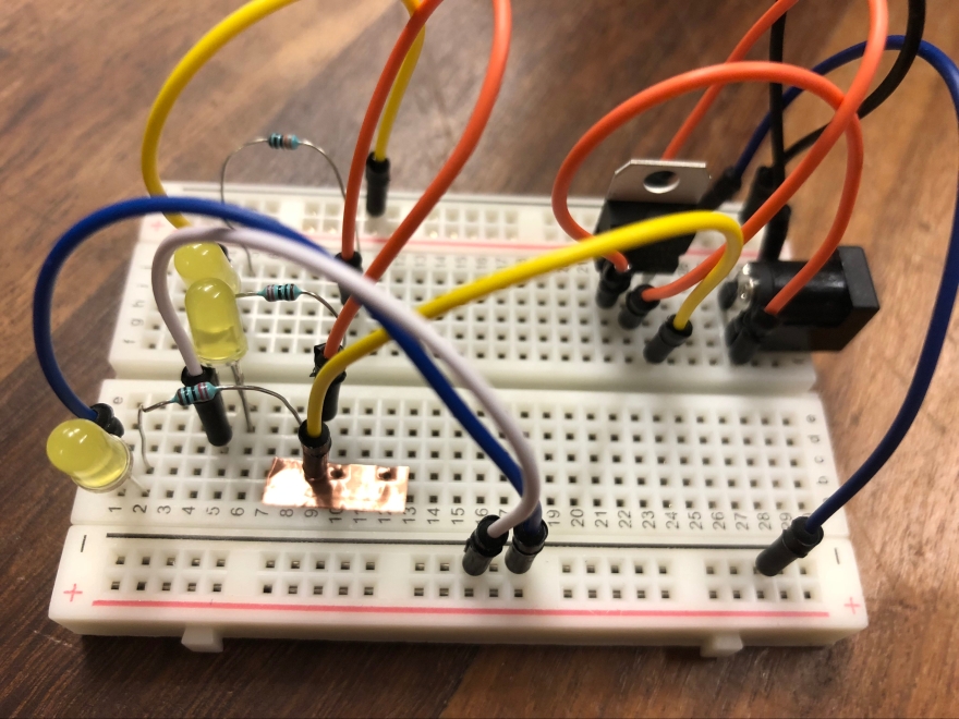
It works! The circuit is completed outside the breadboard with the conductive tape, which will make it easier to add the interactive DIY switch component.
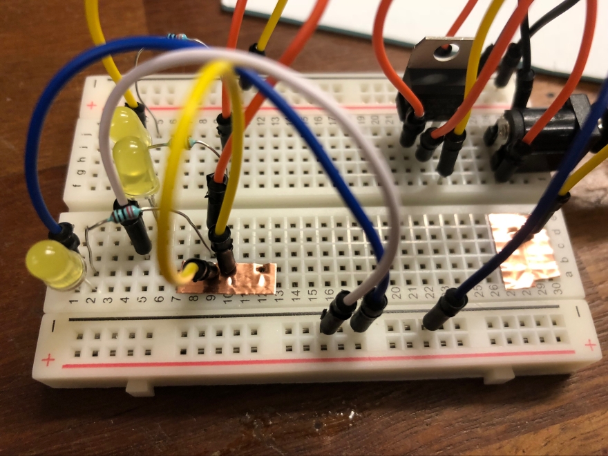
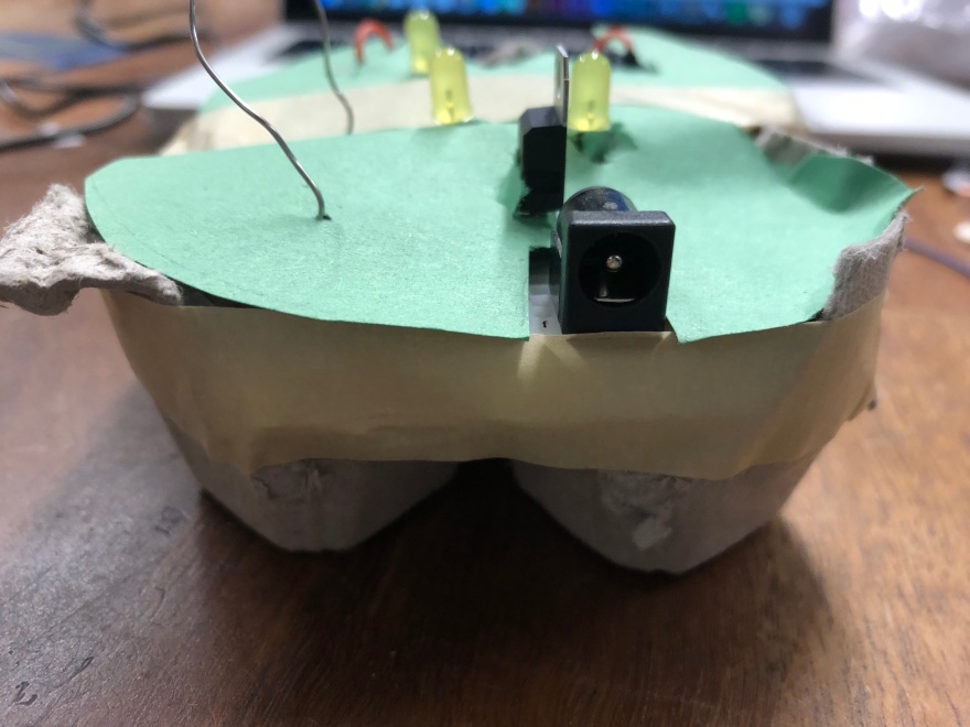
Now I started to think about my creative housing and implementation of my DIY switch. First I replaced the tall jumper wires with lower profile wires to make it easier to conceal my hardware in a clever way. I also made sure the circuit still worked when I was finished.
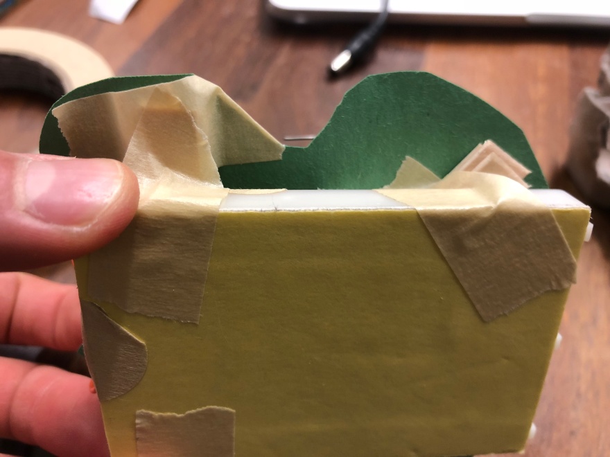
Since the dimensions were perfect, I decided to house my breadboard in an egg carton. Eventually I wanted to make my LEDs look like flowers, and people plant seeds in egg cartons all the time, so I thought it made sense.
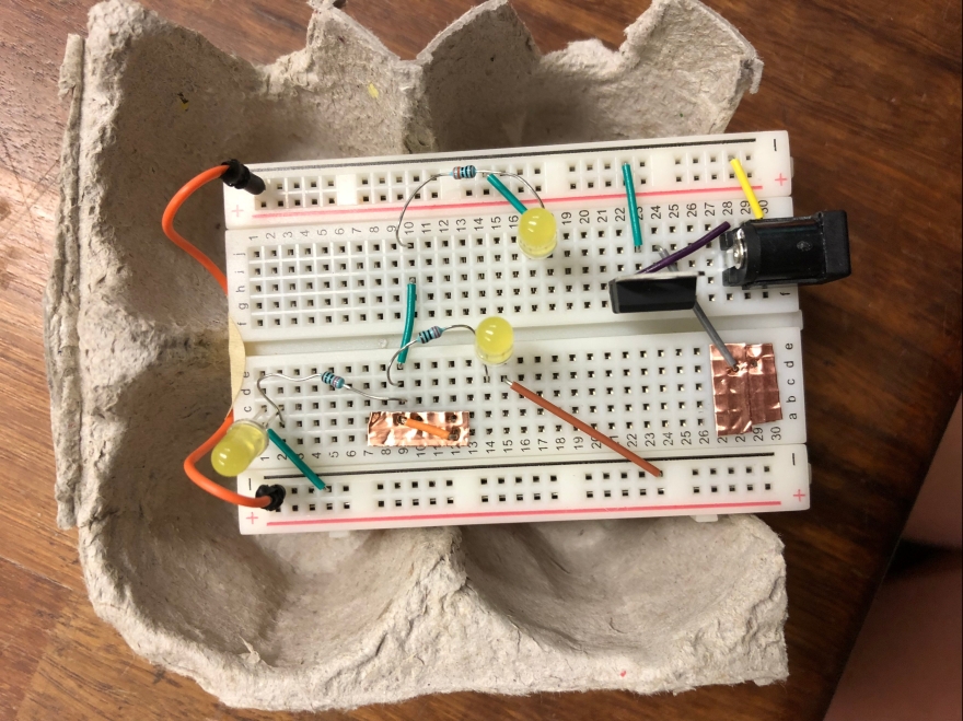
In order to make the switch more accessible, I attached conductive wire to the conductive tape so it rose above the altitude of the top of the egg carton.
And made sure the wires still allowed the circuit to close.
At this point I was ready to start fabricating my creative casing! I decided to build the case before the switch, just so I could put the switch on top of my flower design.
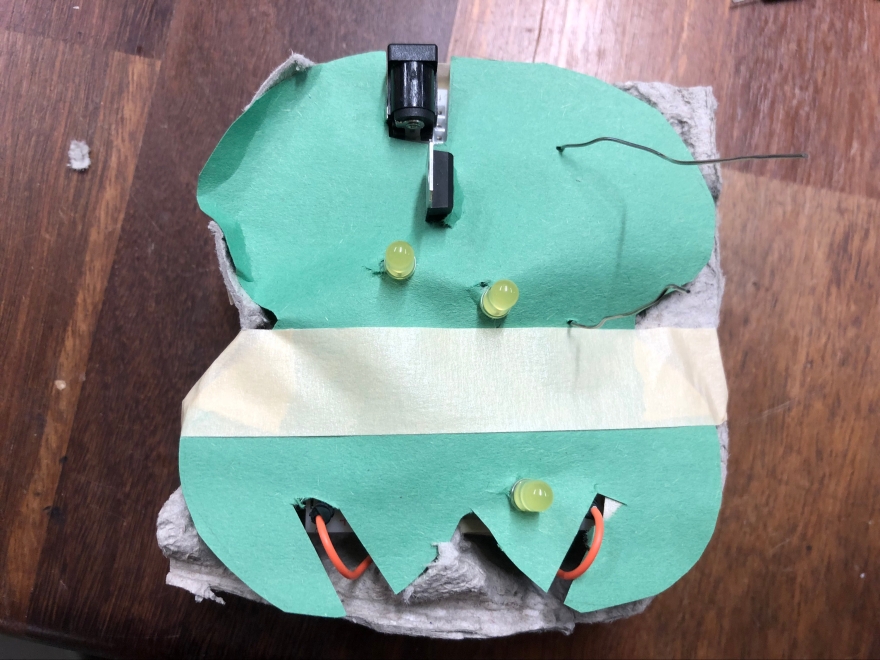
First I covered the top of my breadboard with green construction paper, and stabilized it with tape and popsicle sticks. Before I moved forward I made sure the LEDs still worked and the circuit was closed.
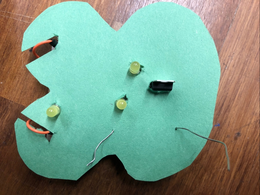
My next step to make my flower scene was to make the LEDs poke out of the middle of the flowers themselves. I made them out of tissue paper. 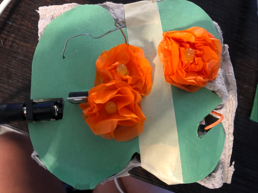
Next I added green tissue paper to more effectively hide the tape, wires, voltage regulator and power source from the top of the project.
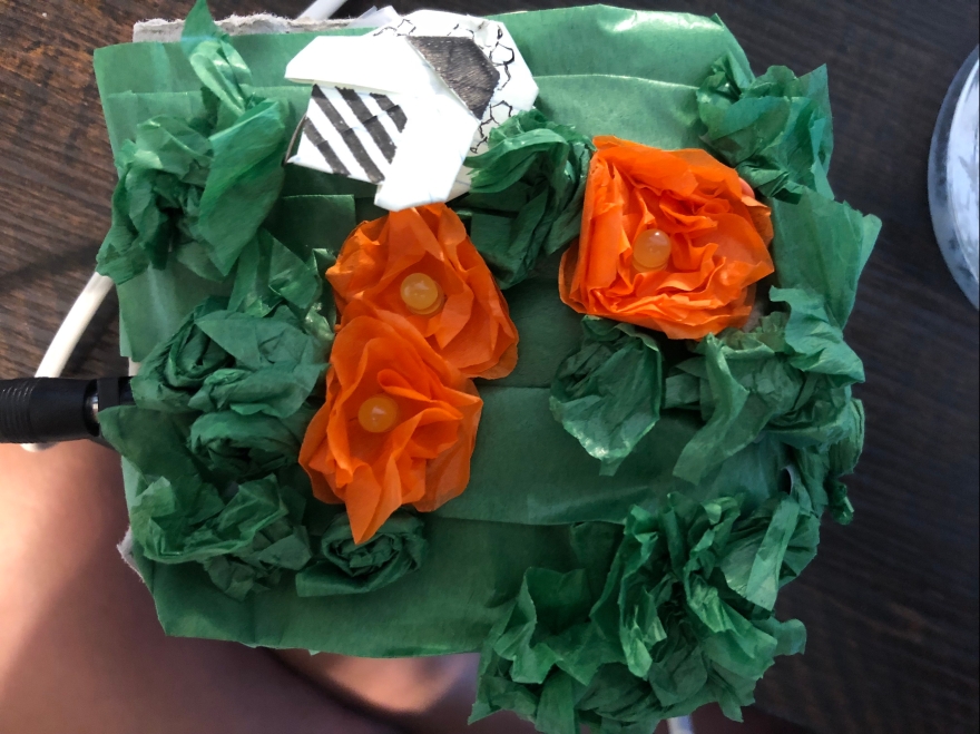
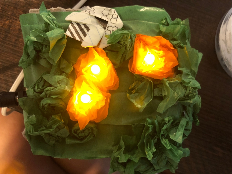
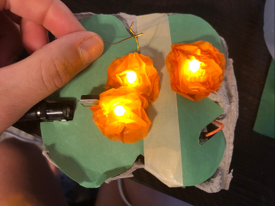
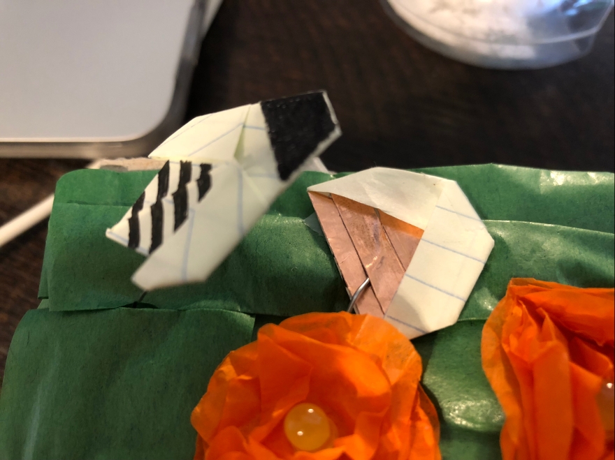
For the DIY switch, I made a bumble bee and beehive with conductive tape connecting to the exposed wires to complete the circuit. The bee has conductive tape on the bottom, and the beehive has it on the inside, so when you put the bee inside the hive, the flowers light up.
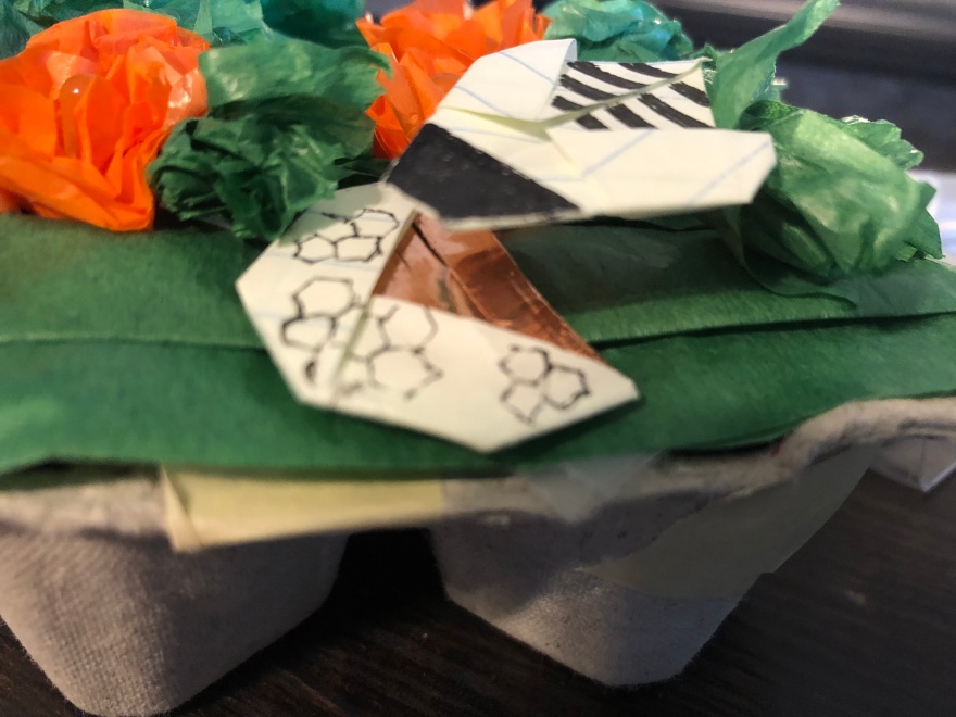
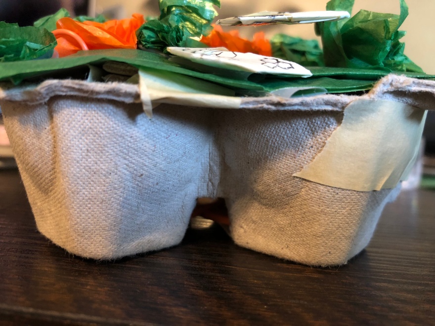
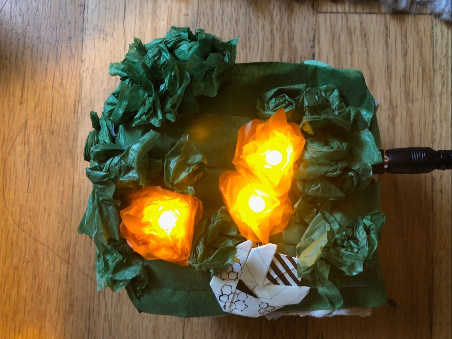
And here is my finished project!