ANALOG I/O + ENCLOSURE
This lab explores analog input and output using variable resistors. I learned how to read sensor values to the serial monitor and utilize pulse width modulation (PWM) and frequency modulation to affect outputs. Some Arduino functions I used were analogRead() and analogWrite(), and printed my sensor values to the Serial monitor to troubleshoot. I also used map() to convert the analog readings into single byte values.
PART 1: VARIABLE INPUT AND OUTPUT
For part one, I build a circuit with two different types of variable resistors as input, and two yellow LEDs as output. My variable resistors were a potentiometer and a light sensor. Below is my schematic for the circuit. The potentiometer is connected to 5V, then pin A0, then grounded. For the light sensor, it’s circuit runs from power, connected to A1, then a 10K ohm resistor, then ground. My two LEDs are connected to pins 9 & 6, both of which are PWM pins (which means they can dim/brighten the LEDs with pulse width modulation to simulate analog output).
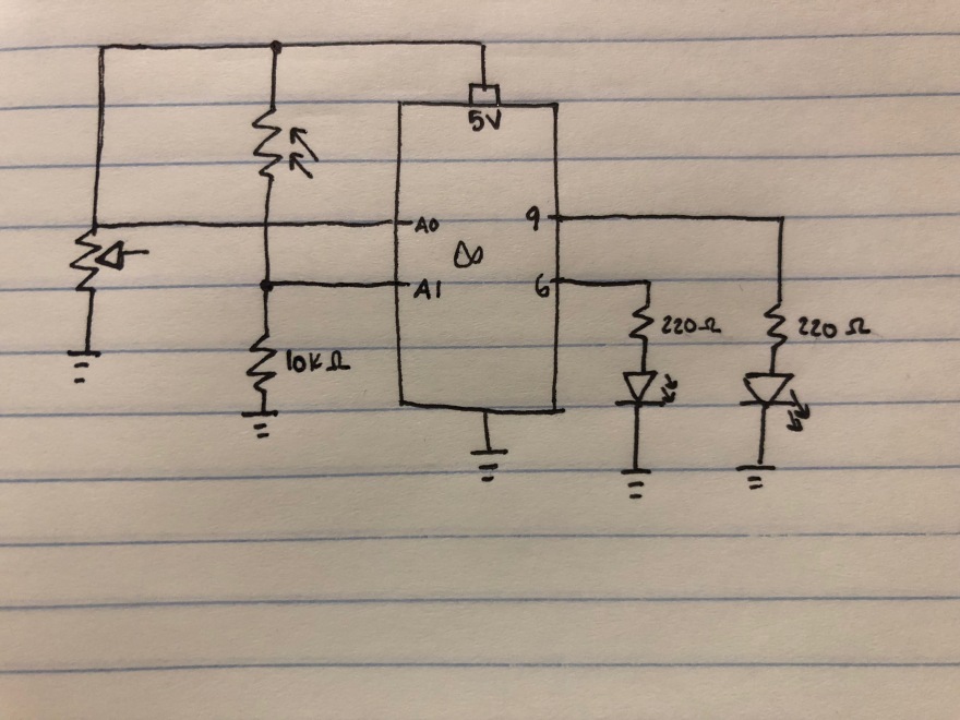
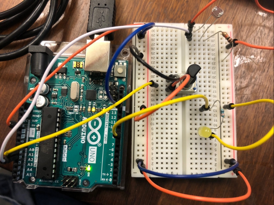
Here is my first circuit to practice using the two variable resistors:
I programmed my Arduino to get variable output with the LEDs based on how the two sensors were used. If the light sensor was receiving full brightness, the potentiometer dimmed both LEDs evenly. If the light sensor was picking up on dimmer light, the second LED’s brightness was dimmed a corresponding amount to how low of light the sensor was picking up. When that was the case, the potentiometer could only control the brightness of the first LED. The bottom few lines that are commented out are my debugging lines, I was printing to the Serial monitor to make sure the variable resistors were working. Another important part of the Serial monitor was to gauge the range of values the light sensor picks up, so I could properly use the map() function.
This file contains hidden or bidirectional Unicode text that may be interpreted or compiled differently than what appears below. To review, open the file in an editor that reveals hidden Unicode characters.
Learn more about bidirectional Unicode characters
| // object lab 3 part 1 | |
| int pot = 0; // stores potentiometer value reading | |
| int photoValue = 0; // stores light sensor value | |
| int potPin = A0; // potentiometer analog input | |
| int photoPin = A1; // light sensor analog input | |
| int yellowLED = 9; // pwm pin | |
| int yellow2 = 6; // pwm pin | |
| int brightness = 0; // value from potentiometer to hold LED brightness | |
| int bright2 = 0; // value from light sensor to hold LED 2 brightness | |
| void setup() { | |
| // set up serial comm | |
| Serial.begin(9600); | |
| pinMode(yellowLED, OUTPUT); | |
| pinMode(yellow2, OUTPUT); | |
| } | |
| void loop() { | |
| // read pot and light sensors | |
| pot = analogRead(potPin); // reads potentiometer | |
| photoValue = analogRead(photoPin); // reads light sensor | |
| // change LED brightness based on potentiometer value | |
| // write to LED | |
| // use map() to convert 0 – 1023 to 0 – 255 | |
| // map(valueToMap, fromLow, fromHigh, toLow, toHigh) | |
| brightness = map(pot, 0, 1023, 0, 255); | |
| analogWrite(yellowLED, brightness); | |
| analogWrite(yellow2, brightness); | |
| //change LED2 brightness based on light sensor value | |
| if(photoValue < 600){ | |
| bright2 = map(photoValue, 43, 796, 0, 255); | |
| analogWrite(yellow2, bright2); | |
| } | |
| // Serial.print("potentiometer value: "); | |
| // Serial.print(pot); | |
| // Serial.print("lightVal: "); | |
| // Serial.println(photoValue); | |
| // Serial.print(" LED brightness: "); | |
| // Serial.println(brightness); | |
| } |
Below is a video of my functioning circuit. First the potentiometer changes the brightness of both LEDS, then it I indicate which LED is connected to the light sensor, then I show the variable output when the two sensors are combined.
PART 2: Tone Output
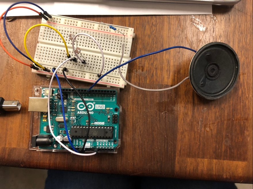
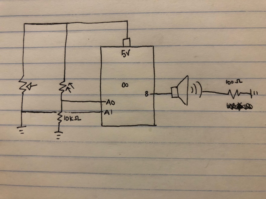
For part 2, I connected two photo-resistors to my Arduino, and their light readings changed the tone of an 8 ohm speaker that I connected to a digital output pin on the Arduino. Below is my schematic and circuit to create my tone output.
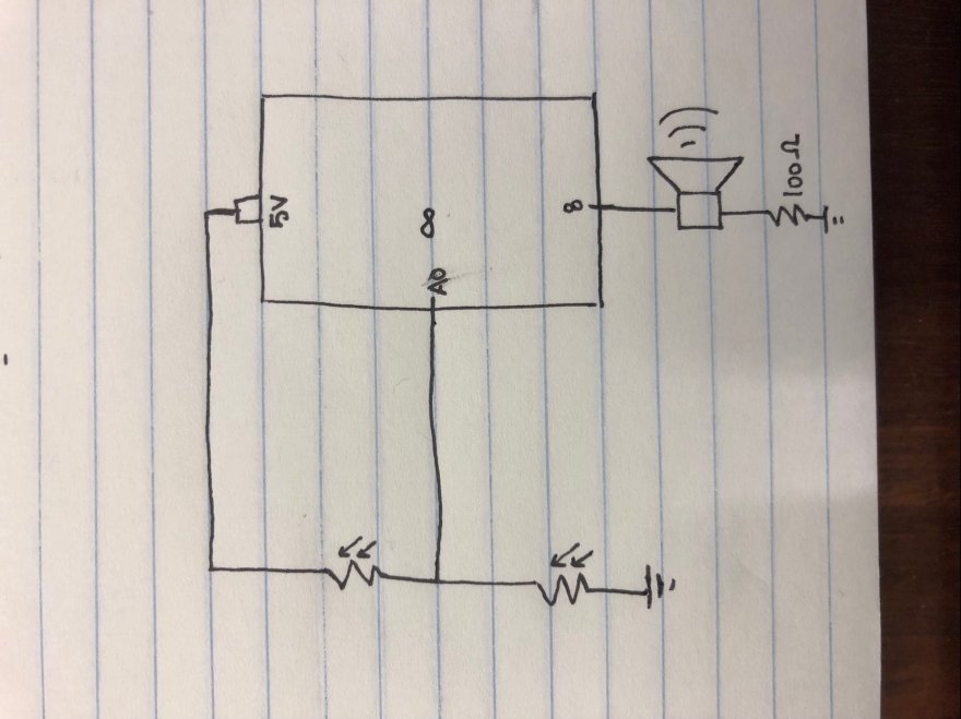
Then, I coded the Arduino to convert the light sensor reading into a frequency value between 100 and 1000. My speaker played that frequency value, and waited half a second before changing tone value. In my setup section, I initialized serial communications so I could see if the photosensors were reading in variable values.
One thing I found interesting was that when both are uncovered, the collective reading was 534, when just the first was covered, it was 80, when just the second was covered, it was 919, and when both were covered it was 415. So for my map() function to convert the 10-bit reading to a frequency, I used 80 and 919 as the high and low. I implemented the tone() function used my variable called “sound” and the pin number (8) for the two parameters. I also added a 500ms delay to change the sound output from a continuous sliding sound change to one that sounded like changing musical notes.
This file contains hidden or bidirectional Unicode text that may be interpreted or compiled differently than what appears below. To review, open the file in an editor that reveals hidden Unicode characters.
Learn more about bidirectional Unicode characters
| // object lab 3 part 2 | |
| int photoValue = 0; // stores value of light sensors | |
| int sensorPin = A0; // analog input | |
| float sound = 0; // stores frequency variable for speaker | |
| int speakerPin = 8; // speaker output | |
| void setup() { | |
| // initialize serial communications | |
| Serial.begin(9600); | |
| pinMode(speakerPin, OUTPUT); | |
| } | |
| void loop() { | |
| // read the analog input on A0 | |
| photoValue = analogRead(sensorPin); // both photosensors are connected to pin A0 | |
| // print it to the serial monitor | |
| Serial.println(photoValue); // make sure both sensors affect the analog reading | |
| // map sensorReading to an output between 100 and 1000, set frequency to this | |
| // sound is my mapped variable that stores the frequency value to send to my speaker | |
| sound = map(photoValue, 80, 919, 100, 1000); // 80 and 919 were the average high and lows of the photosensors | |
| // change the pitch, play for 10ms – use tone() | |
| tone(8, sound); // parameters are the pin, and frequency | |
| delay(500); | |
| } |
Here is a video of my speaker in action!
PART 3: Laser Cut Sensor Box
In order to complete part three, I laser cut a creative enclosure and had two analog inputs: a photosensor and a potentiometer. These inputs produced variable output for a speaker that was also enclosed in my box.
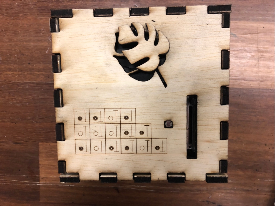
Since I liked the idea of playing a tune with my box, I figured out the frequencies for the first couple notes of “In the Jungle.” To teach the user how to play it, I etched a little key onto the top of my box as well.
Below is my schematic for the circuit in part 3. My two variable resistors were connected to analog input pins on the Arduino, and the speaker was connected to a digital pin set for output.
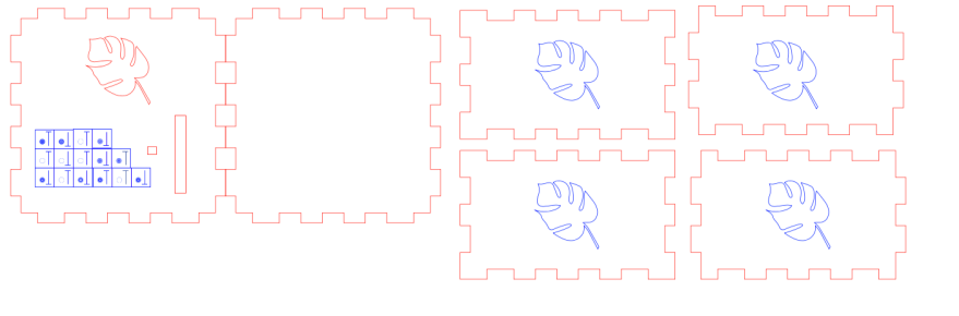
Below is my laser cut design that I used. The red lines create vector cuts all the way through my wood, and the blue just etched on top of the wood.
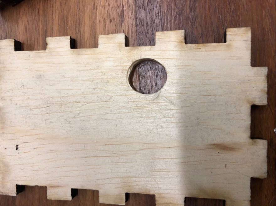
Once I finished laser cutting my box, I realized that I had neglected to put a hole for the power cord to enter my box. For a quick solution, I just used the drill press and a Dremel tool to create an opening.
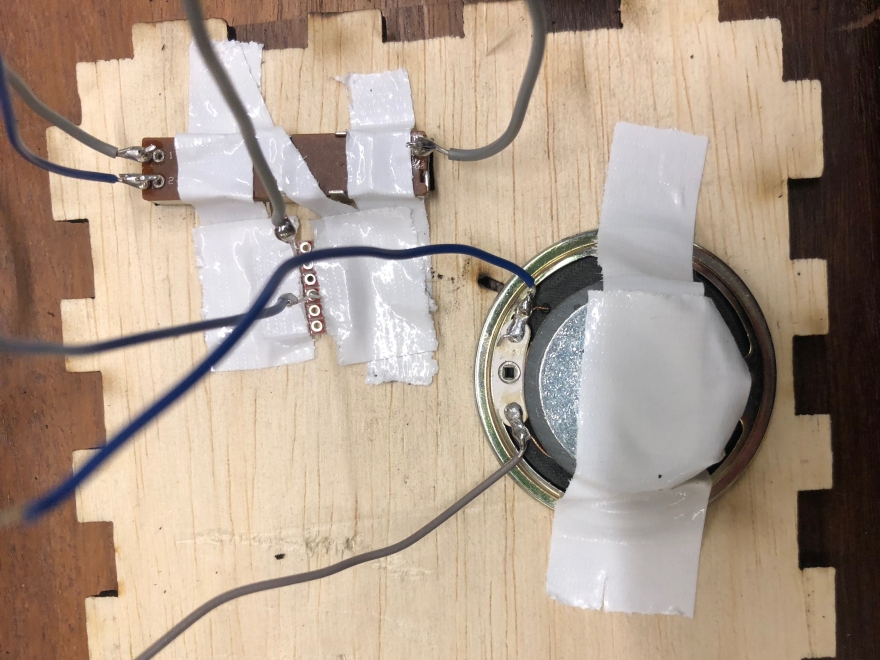
Next, I made my circuit. First, I made sure that the analog input pins were picking up on changing signals from the potentiometer and photosensor by using Serial communication in my Arduino code. Once both of my variable resistors were functioning correctly, I added the speaker (out of frame, the wires are visible). In order for my components to fit into my enclosure flush with the top, I soldered them to wire so I could place them where I needed to in my enclosure.
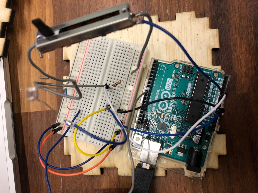
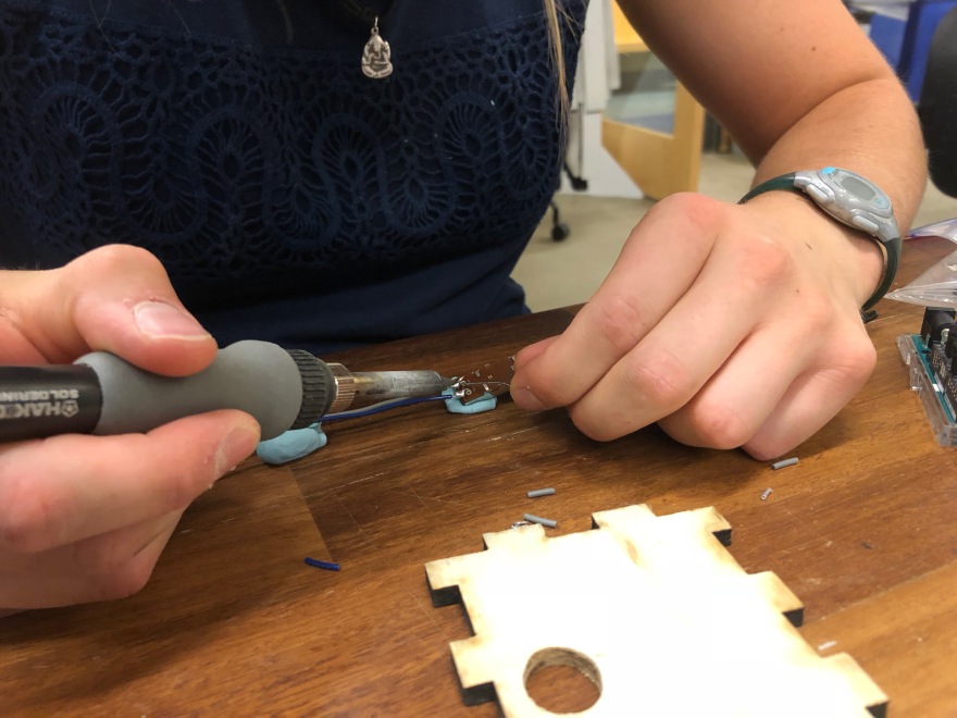
Securing my components into my enclosure was a little bit of a challenge. For the photosensor, I soldered it to a piece of proto-board in order to secure it in a fashion that allowed it to be flush with the top surface of my box. For the potentiometer, I had used the footprint of the wrong component when designing my laser cut design, so it’s rectangular face did not fit flush in the hole I cut for it.
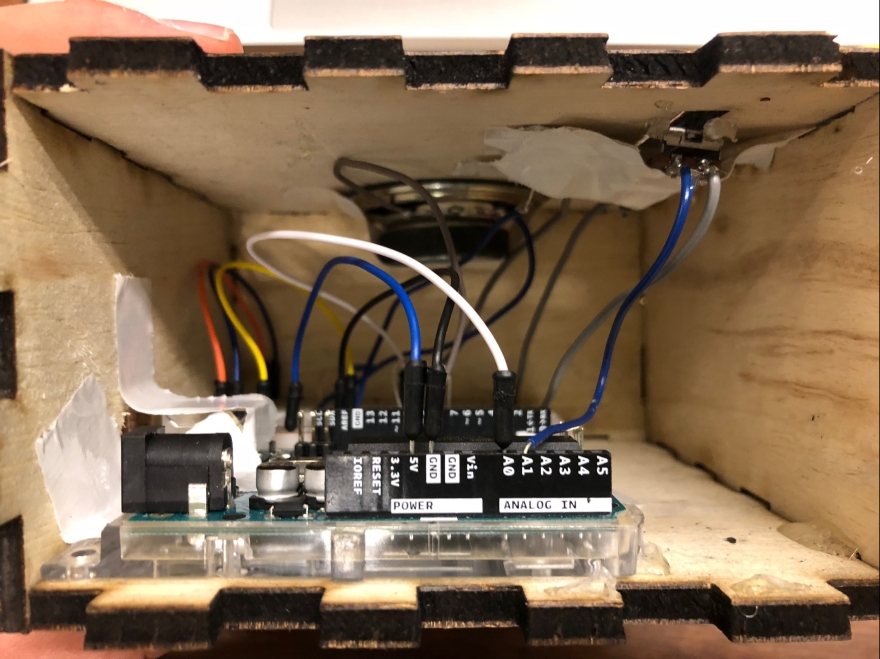
However, I did properly allocate 3D space inside the box, so all of the components, the Arduino, and the breadboard fit very well inside. I hot glued 5 of the walls together to increase structural integrity, while leaving one side open. Just in case I needed to adjust anything as I progressed.
Everything came together quite nicely at the end! The grid with the symbols on top show how to play the “In the Jungle” tune. The filled in circle means cover the light sensor, the empty circle means uncover the light sensor, and whether the notch is at the top or bottom means to slide the potentiometer up or down.
Here is my code for part 3:
This file contains hidden or bidirectional Unicode text that may be interpreted or compiled differently than what appears below. To review, open the file in an editor that reveals hidden Unicode characters.
Learn more about bidirectional Unicode characters
| // object lab 3 part 3 | |
| int photoValue = 0; // stores value of light sensor | |
| int photoPin = A0; // analog input | |
| int potValue = 0; // stores value of potentiometer | |
| int potPin = A1; // analog input | |
| int speakerPin = 8; // speaker output | |
| float sound = 0; // stores frequenct variable for speaker | |
| void setup() { | |
| // initialize serial communications | |
| Serial.begin(9600); | |
| pinMode(speakerPin, OUTPUT); | |
| } | |
| void loop() { | |
| photoValue = analogRead(photoPin); // read the analog input of photometer | |
| potValue = analogRead(potPin); // read the analog input of potentiometer | |
| // debug print to serial monitor | |
| Serial.print("Photo value: "); | |
| Serial.print(photoValue); | |
| Serial.print(" Potentiometer value: "); | |
| Serial.println(potValue); | |
| // Here are the four notes of my the song | |
| // C plays if the photo sensor is covered and the potentiometer is high | |
| if((photoValue < 300) && (potValue > 1000)){ | |
| tone(8, 523.251, 500); // C | |
| } | |
| // D plays if the photo sensor is covered and the potentiometer is low | |
| else if((photoValue < 300) && (potValue < 1000)){ | |
| tone(8, 587.33, 500); // D | |
| } | |
| // E plays if the photo sensor is uncovered and the potentiometer is high | |
| else if((photoValue > 700) && (potValue > 1000)){ | |
| tone(8, 659.255, 500); // E | |
| } | |
| // F plays if the photo sensor is uncovered and the potentiometer is low | |
| else if((photoValue > 700) && (potValue < 1000)){ | |
| tone(8, 698.456, 500); // F | |
| } | |
| } |
Below is a recording of my box performing just how I envisioned it would from the beginning, I think my rendition of “In the Jungle” is more catchy than the original:
